
Installation and Setup
During the installation, we found that the placement of a couple items were rather dubious. For example, the audio header is at the bottom left corner, the farthest reach for any audio cable length for a PC enclosure. On one hand, there won’t be much slack, but on the other hand, it may not even reach at all on bigger cases. How about moving it a bit closer?
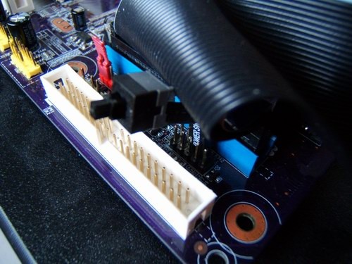
IDE Cable vs. BenchTop Power Button: Ouch!
Also, the IDE headers are placed quite near the CMOS’s clearing pins and the system header; once the large and wide IDE cable is inserted, there is little breathing room to manipulate the system header.
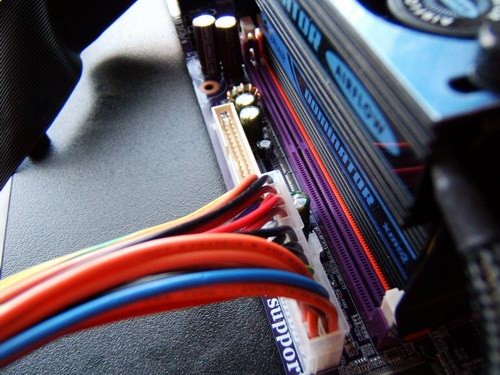
Also, by the RAM, the 24-pin ATX header seemed a little too close for comfort due to the normally inflexible girth of the system power connector. The inclusion of the floppy disk header in the vicinity makes it even more cramped should one still require it.
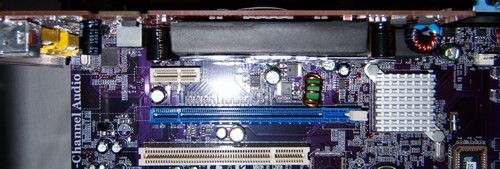
Good enough for single slot graphics cards…
The spacing between the two PCI Express x16 slots appeared to be equally as mainstream as the board in that two typical high end dual-slot-sized video cards would only just fit with little air circulation between two cards. As we saw with the 680i motherboard, ample space was given between each of the three x16 slots to allow for a modest amount of room for the fan to grab air to be blown out of the system.
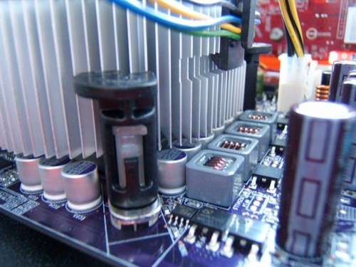
Cuttin’ it a lil’ close eh?
One other concern of mine is that there is a row of capacitors extremely close to the CPU socket. Although it was not a problem for the stock CPU cooler, it barely made just enough clearance to keep our stock INTEL heatsink from ramming into them. This should not be a problem for taller heatsinks that incorporate heatpipes and start getting ginormous a little higher up.